Stratify Toolbox Prototype Update
Signup on Crowd Supply
The Toolbox Preview Page is up on Crowd Supply.
This is an updating post for Stratify Toolbox prototype development updates. Come back soon to see how the progress is going.
Update 2020-02-26
After building the components in the new StratifyAPI ux namespace, building the keyboard application took less than 2 hours. It was great. The full video of the gif above is on youtube.
Update 2020-02-18
The Gpio Tool allow you to directly manipulate pins, quickly and graphically. This is a simple tool that can be great for:
- monitoring a pin during development
- testing LEDs and power supplies
- injecting a reset signal on a board
You can see the original video here.
Update 2020-02-13
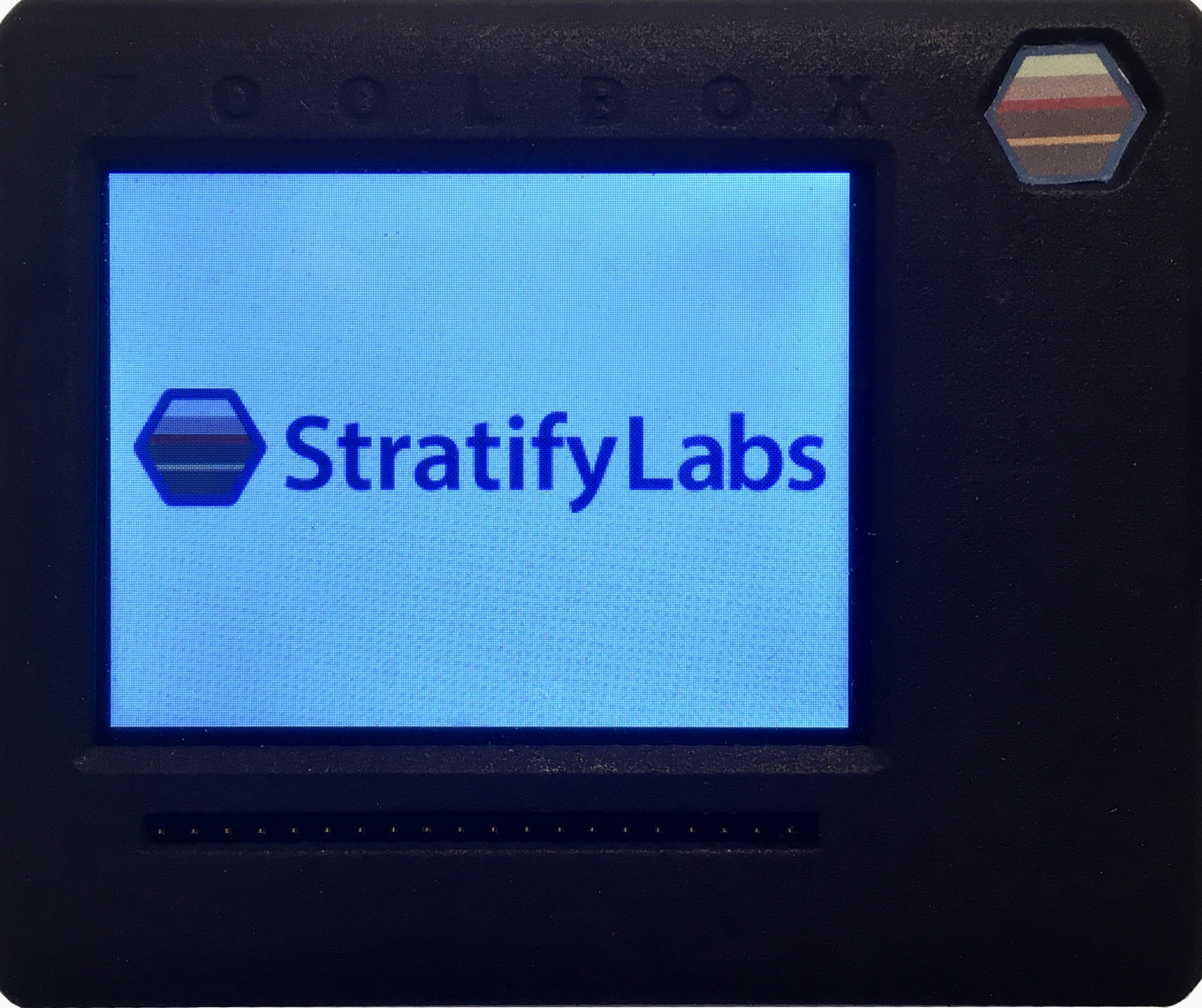
New Prototype Built
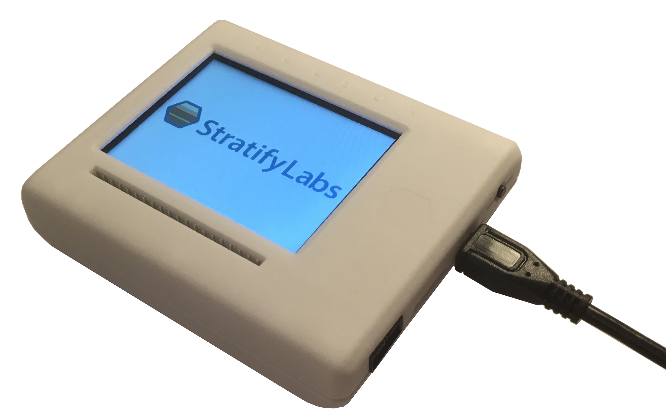
The top image on this page has been updated with the latest prototype. The logo on the top right is a touch sensor that is used to power on the device.
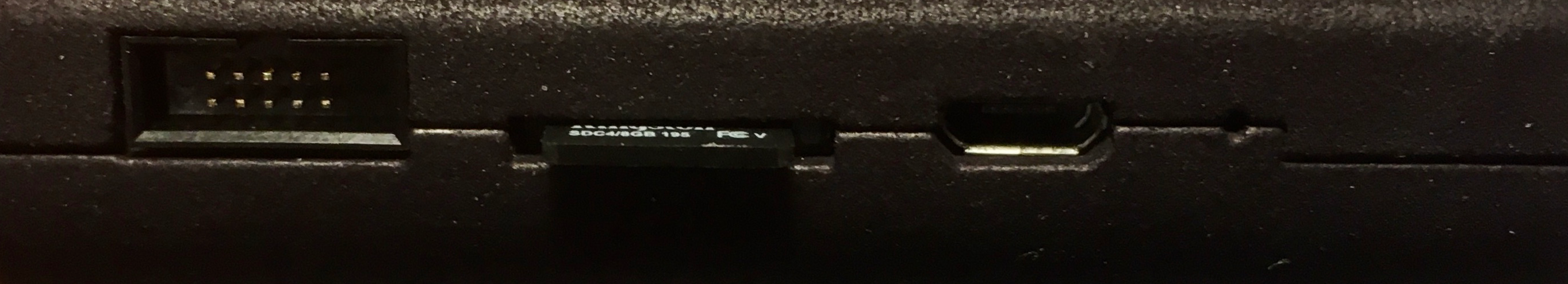
Here are the side ports on the Toolbox from left to right
- 10 pin JTAG/SWD master connector
- SD Card supporting High capacity cards (4GB to 64GB)
- USB Device Connector (for development and USB to JTAG/SWD/Serial port access)
- Reset Pin Hole (just in case)
Developing the GpioTool

The GpioTool is an application that is simply used to manipulate the GPIO pins. This application sets the graphical framework for all other applications (hence its taking awhile to develop).
Update 2019-09-03
The Stratify Toolbox prototype is really starting to come together. The firmware development is ongoing but the following highlights parts that are up and running.
- STM32H750 microcontroller
- Running at 416MHz
- Enough RAM to run a handful of powerful applications concurrently
- External 8MB Flash drive
- Allows applications to easily save and retrieve user data
- Fast QSPI connection
- 320 x 240 Pixel IPS Display
- The Display looks great (check out the image above)
- IPS has excellent viewing angles
One of the big challenges in getting the display working was getting the STM32 FMC to work in 8-bit parallel mode. The problem I ran in to was that every transaction was a 64-bit one.
I dug in to this and found that the AXI bus is 64-bits. And it would write extra bytes if the memory width (8-bit parallel interface) was smaller than 64-bits. This meant 8 bytes were written every time I tried to access the bus.
I partly solved the problem by telling the STM32 FMC driver the bus width was 32-bits instead of 8-bits. This meant that the top 24-bits were ignored because those pins weren’t connected to the FMC (just the lowest 8-bits). But now, every transaction was 2 bytes instead of one.
The final step was to plan every register and data write based on the fact that 2 bytes were written everytime. Writing command zero is a NOP so I just sent a NOP before every command. Then I padded the data with a zero byte if needed to complete the transaction.
typedef struct MCU_PACK {
	u8 first;
	u8 dummy[3];
	u8 second;
	u8 dummy0[3];
} transaction_data_t;

typedef union {
	u64 raw;
	transaction_data_t data;
} transaction_t;

void write_command(u8 Reg){
	SET_COMMAND();
	cortexm_delay_us(2);
	transaction_t transaction;
	transaction.data.first = 0; //NOP
	transaction.data.second = Reg; //register value
	*m_reg_location = transaction.raw;
	__DSB();
	cortexm_delay_us(1);
	SET_DATA();
	cortexm_delay_us(1);
}

void write_data_block(const u8 * data, int nbyte){
	transaction_t transaction;
	for(u32 i=0; i < nbyte; i+=2 ){
		transaction.data.first = data[i];
		transaction.data.second = data[i+1];
		*m_reg_location = transaction.raw;
		__DSB();
	}
}